25+ microwave transmitter and receiver block diagram
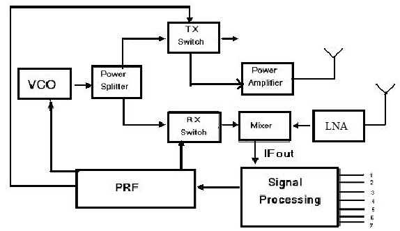
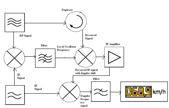
Different sources define different frequency ranges as microwaves. We know that a radar system has a transmitting and receiving section.

Pin On Electronics Things Circuits And
Duplexer is a two-way microwave gate.

. The main function of this is to carry the data in the bits form through the Local Area Network LAN. The expression Block refers to the conversion of a block of microwave frequencies as received from the satellite being down-converted to a lower block range of frequencies in the cable to the receiver. Transceiver transmitter amplifier and antenna.
X10 RF daughter board - receiver circuit diagram. Satellites broadcast mainly in the range 4 to 12 to 21 GHz. GPS Sensor GPS keeps the car on its intended route with an accuracy of 30 centimeters.
In data communication it works like a physical path between the sender the receiver. Motorola Receiver DCH3200 Operation users manual 44 pages 5. IQ sampling is more easily understood by using the transmitters point of view ie considering the task of transmitting a RF signal through the air.
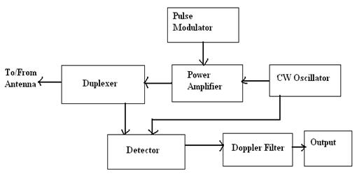
The block diagram of transponder is shown in below figure. Block Diagram of Radar System. Many of the cordless telephones and baby monitors in the United States and Canada use the 24 GHz frequency the same frequency at which Wi-Fi standards 80211b 80211g 80211n and 80211ax operate.
Apparatus for and method of sensing brain waves at a position remote from a subject whereby electromagnetic signals of different frequencies are simultaneously transmitted to the brain of the subject in which the signals interfere with one another to yield a waveform which is modulated by the subjects brain waves. FUNCTIONAL BLOCK DIAGRAM OBSERVATION Rx ORX1 ORX1 ORX2 ORX2. Also called a low-noise block low-noise converter LNC or even low-noise downconverter LND the device is.
It is the field described by classical electrodynamics and is the classical counterpart to the quantized electromagnetic field tensor in quantum electrodynamicsThe electromagnetic field propagates at the speed of light in fact this field. What is Transmission Media. A transmitrecieve switch that tells the antenna.
We can easily understand the operation of Transponder from the block diagram itself. This channel also connects to three sniffer receiver inputs that can monitor radio activity in different bands. Motorola Receiver DCH70 Operation users manual 28 pages Motorola Receiver DCH70 Quick start manual 2 pages Motorola Receiver DCH70 Installation manual 52 pages 6.
A communication channel that is used to carry the data from the transmitter to the receiver through the electromagnetic signals. 272 Basic Spectrum Analyzer Block Diagram 273 Microwave Spectrum Analyzer 274 Harmonic Mixer Responses 275 Front-End Filtering 276 Preselector Response 277 Microwave and Low Band Architecture 278 Tracking Generator Architecture 279 Supporting Notes 2710 Module Quiz. The above broad definition includes both UHF and EHF millimeter wave bandsA more common definition in radio.
The figure below shows the block diagram representation of radar. RX3302 433MHz superregenerative receiver module circuit diagram. 88 - 108MHz FM audio transmitter bug circuit diagram.
The vast majority of radar systems on the road today are based on 24 GHz discrete RF technology including phase-locked loop ramp generator transmitter receiver and ADC. A silent communications system in which nonaural carriers in the very low or very high audio frequency range or in the adjacent ultrasonic frequency spectrum are amplitude or frequency modulated with the desired intelligence and propagated acoustically or vibrationally for inducement into the brain typically through the use of loudspeakers earphones or. In radio communications a radio receiver also known as a receiver a wireless or simply a radio is an electronic device that receives radio waves and converts the information carried by them to a usable form.
The technologies listed in the table below differ in the distance over which they can transfer power efficiently whether the transmitter must be aimed directed at the receiver and in the type of electromagnetic energy they use. An observation receiver channel with two inputs is included to monitor each transmitter output and implement interference mitigation and calibration applications. An electromagnetic field also EM field or EMF is a classical ie.
Low noise block downconverter LNB diagram. ADI continues to leverage its extensive automotive design expertiseand over 300 million automotive radar ICs shipped worldwideto develop the next generation of ADAS. This can cause a significant decrease in speed or sometimes the total blocking of the Wi-Fi signal when a conversation on the phone takes place.
Your microwave cooks food with electromagnetic waves at 24 GHz. Include in your explanation. Image Sensor Computer Vision Block diagram for computer vision Output 1 Output 2 18.
Microwave is a form of electromagnetic radiation with wavelengths ranging from about one meter to one millimeter corresponding to frequencies between 300 MHz and 300 GHz respectively. A low-noise block downconverter LNB is the receiving device mounted on satellite dishes used for satellite TV reception which collects the radio waves from the dish and converts them to a signal which is sent through a cable to the receiver inside the building. The function of each block is mentioned below.
It receives uplink signal from the satellite antenna and transmits downlink signal to the satellite antenna. Explain how radio waves carry information. Draw a block diagram for a radio station that includes a transceiver amplifier microphone antenna and feed line.
The receiver of t he data transmitted. The interference waveform which is representative of the brain. Associate membership to the IDM is for up-and-coming researchers fully committed to conducting their research in the IDM who fulfil certain criteria for 3-year terms which are renewable.
Circuit diagram for superregenerative receiver built by GE labs. A transmitter which creates an electromagentic energy pulse in the radio or microwave domain. Non-quantum field produced by accelerating electric charges.
Printer Terminal Mainframe and Computer. Is simply an. The transmitter section is composed of the following units.
The transmit and receive antennas are slightly separated but still appear to be at the same location as. It is used with an antennaThe antenna intercepts radio waves electromagnetic waves of radio frequency and converts them to tiny alternating currents which are applied to. Basic Block Diagram of a Data Communication.
Let us now discuss how radar operates. And both the sections perform their respective operation. The transmitter and receiver are colocated as viewed from the target ie the same antenna is used to transmit and receive.
If there is a leak in the door then your microwave will jam WiFi signals and possibly also burn your skin. Explain the differences between a block diagram and a schematic diagram. Wireless power transfer is a generic term for a number of different technologies for transmitting energy by means of electromagnetic fields.
Viewed from the target eg ground transmitter and airborne receiver.
Radar Sensor Types Working Advantages Its Applications

Transmitter Receiver An Overview Sciencedirect Topics

2km Long Range Fm Radio Transmitter Fm Transmitters Transmitter Electronics Mini Projects
Generic Block Diagram Of A Wireless Power System Circuit Projects Wireless Power
![]()
Wireless Power Transmission Through Solar Power System Working
Radar Basics Types Working Range Equation Its Applications

Fm Basic Frequency Modulation Components Testing Of Fm Transmitter

1000w Power Inverter Audio Amplifier Power Inverter Circuit Diagram

Pin On Radio Rf Circuits Projects
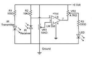
Ir Sensor Circuit Diagram Types Working With Applications
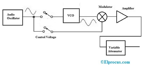
Signal Generator Circuit Working Types And Its Applications
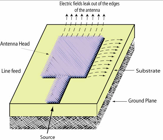
Introduction To Types Of Microwave Antennas In Communication Systems

1000w Power Inverter Audio Amplifier Power Inverter Circuit Diagram

Transmitter Receiver An Overview Sciencedirect Topics

Mosfet Fm Transmitter Circuit Fm Transmitters Circuit Diagram Transmitter
Radar Basics Types Working Range Equation Its Applications
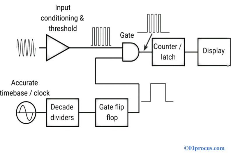
Frequency Counter Block Diagram Circuit Types And Its Applications